Connecting Android sensors to ROS transforms
In the last workshop, we worked with AR-tags and used some functionality from a tf module. In this workshop we go slightly deeper and exlore how TFs are created and what is their role in visualizing sensor data.
More precisely, we are going to explore how sensors from an Android phone can be imported to ROS and how to attach the sensor data to an existing robot.
Setting up an Android phone as a sensor
A smartphone can automatically adjust its display rotation based on how the person is holding it. The brightness of the display can automatically adjust based on the ambient light levels. It is possible to download an app that turns a smartphone into a compass where the needle always points to the north. These are just a few of the examples that make use of the many sensors embedded in a smartphone. These sensors can, of course, be used in a robotic system as well. For instance, by taping a smartphone to a toy car, we create a machine that can position itself in the world using the GPS.
In this section, we are going to use an Android device as a multisensor, integrate it with a ROS system, and visualize the sensor data.
First, we can easily turn an Android phone into a ROS sensor with an app called ROS Android Sensors Driver, available in Google Play store. Once the app has been installed on the Android device, we need to establish connection between the Android device and the ROS computer.
Connect the Android device and the ROS computer into the WiFi network named
ros_training.Once the ROS computer and Android device are connected and able to see each other, we need the IP address of the ROS computer. This IP address must be inserted into the Android app in the following format:
http://192.168.88.xxx:11311/
Replace the xxx with the actual IP address of the ROS computer. You can find out the IP with the hostname -I or ip addr commands.
Make sure that roscore is running on the ROS computer before you press OK in the Android app.
If the set up was successful, we should now see several new topics when listing all active ROS topics on the computer. The active topic list might look something similar to the following:
peko@laptop-1:~$ rostopic list
/android/fix
/android/illuminance
/android/imu
/android/magnetic_field
/rosout
/rosout_agg
In order to be absolutely certain that messages from the Android device are coming through, we should print on screen the messages from one of these topics, for example:
rostopic echo /android/imu
If there are messages printed with continuously updating values, the connection is sucessfully established and the phone is sending data to the ROS device.
Let’s focus on the data that is received. We can see that the message contains orientation, velocity, and acceleration values. In addition to that, there is a header section with a frame_id field. This field is really important as it specifies the coordinate frame where the IMU data is given.
header:
  seq: 267624
  stamp:
    secs: 1623646810
    nsecs: 621000000
  **frame_id: "/imu"**
Visualizing IMU data in RViz
RViz is a simple yet powerful visialization tool in ROS. It has a capability of visualizing IMU and tons of other type of ROS data. The data is visualized by display plugins, many of which are already part of the standard ROS desktop installation.
Open RViz by entering the command
rvizto the terminal.
In order to start visualizing IMU, we need a display plugin named IMU. The simplest way to add this would be selecting our IMU topic under by topic tab:
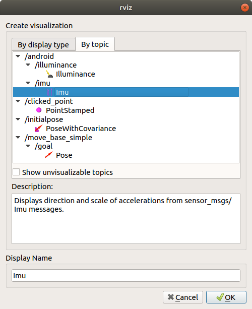
Fig. 2 IMU display plugin added by topic.
As seen, nothing is yet to be displayed. This is expected, because we have not provided any information on how /imu frame relates to the Fixed Frame. The Fixed Frame let’s RViz know with respect to what all of the content will be visualized.
Change the Fixed Frame value to point to the /imu frame
If everything is correctly configured, we should see an arrow as depicted in Fig. 2. Pick up the Android device, rotate it and observe the visualization in RViz.
Fig. 3 Visualization of IMU data in RViz.
Creating a static transform
In a real-world scenario, we need to visualize multiple objects together in the same scene (e.g. an IMU mounted on the top of a robot). This means that we have to let the software know about all the relations between the objects. In ROS, this is achieved via concept of TF, which keeps a tree of transforms between objects and provides tools to get or set transforms between any two objects in the tree. There are two types of transforms: static and dynamic, which are being published on /tf_static and /tf topics, respectively. While /tf is meant for continously updating transforms (e.g. links of a robot manipulator), the /tf_static is broadcasted, latched, and will not change unless ordered.
First, let’s try adding a static transform that places our Android IMU sensor to the world.
We will name the world frame map and create a transform from map (parent) to
imu frame (child).
Run
roscore.Using static_transform_publisher, create a transform between
mapandimu.rosrun tf static_transform_publisher 0 0 1 0 0 0 map imu 10
Use http://wiki.ros.org/tf2_ros#static_transform_publisher as a reference. This command keeps the rotation zero for now but sets the translation so that
imuframe would be 1 meter higher than themapframe.Launch
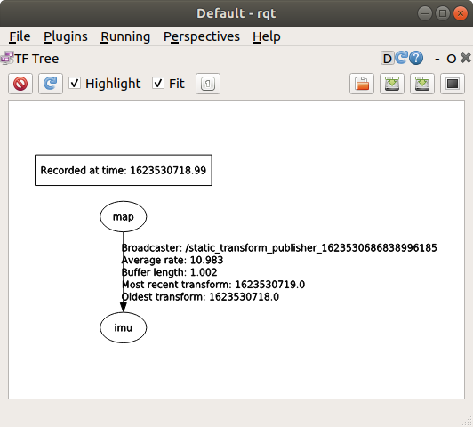
rqtin another terminalOn the top bar, go to Plugins -> Visualization -> TF Tree. This will show you the current transforms in the system. And should see something like this:
Open up RViz again and set the Fixed Frame to
map. Because of the published transform, we can choose the desired Fixed Frame conveniently from the drop-down menu in RViz.In the RViz windows, you should see the origin of IMU acceleration vector and range be set to 1 meter above ground.
Add a display plugin named
TFto visualize all the frames in the TF tree.Use CTRL-C to stop static_transform_publisher. What happened in RViz after we stop publishing a transform?
Rerun the transform and experiment with different transform parameters (including orientation).
If everything works, use CTRL-C to shut down all ROS programs and continue with the next task.
Exercise
Suppose we have attached the Android phone now on top of Robotont’s computer. Your task here is to implement the proper TF publisher in order to see the imu data with respect to the robot.
Open up a visualization of the Robotont robot model:
roslaunch robotont_nuc_description display_simulated_robot.launch
This launch file will do three things:
load the robot model into the ROS parameter server
start robot_state_publisher, which publishes transforms of all the robot components (called links).
starts RViz with a custom configuration file that already brings up some plugins e.g. for visualizing the robot model.
Tip
The robot description is a URDF-formatted string. You can be explore the string with the
rosparam echo /robot_descriptioncommand.Publish a static transform that would connect the Android sensors IMU with the Robotont on-board computer (frame:
computer_link).Add again the imu visualization plugin to enjoy the show.
Dynamic transform
In the previous sections, we displayed an arrow which starting point was set to the origin of the imu frame and end point corresponded to the data received on /android/imu topic.
Currently, there is no frame at the end point of the arrow. However, in many cases it would be useful to have also the end point available in the tf tree.
This is where transform programming comes in play.
Dynamic transforms are published in the nodes continuously.
Our goal here is to broadcast a new frame imu_end_pt as a child of the imu frame. The new frame should rotate as we change the orientation of the IMU and translate according to the imu’s linear_acceleration field.
First, recall day 2 and create a new catkin package with roscpp, tf2, and tf2_ros dependencies.
Use this this tutorial as an example to publish imu to imu_end_pt transform according to IMU data.
To test your code, build, source, and run the node.
Launch RViz and visualize with the tf display as in previous sections. like in the previous task.
Now you should see your imu_end_pt frame responding to the IMU’s acceleration and orientation. If yes, congratulations, you have completed the task. If not, go double check the transforms or ask instructors to assist.
You can also try it with a real robot, set fixed frame to odom, so that the robot would move in RViz according to wheel odometry.